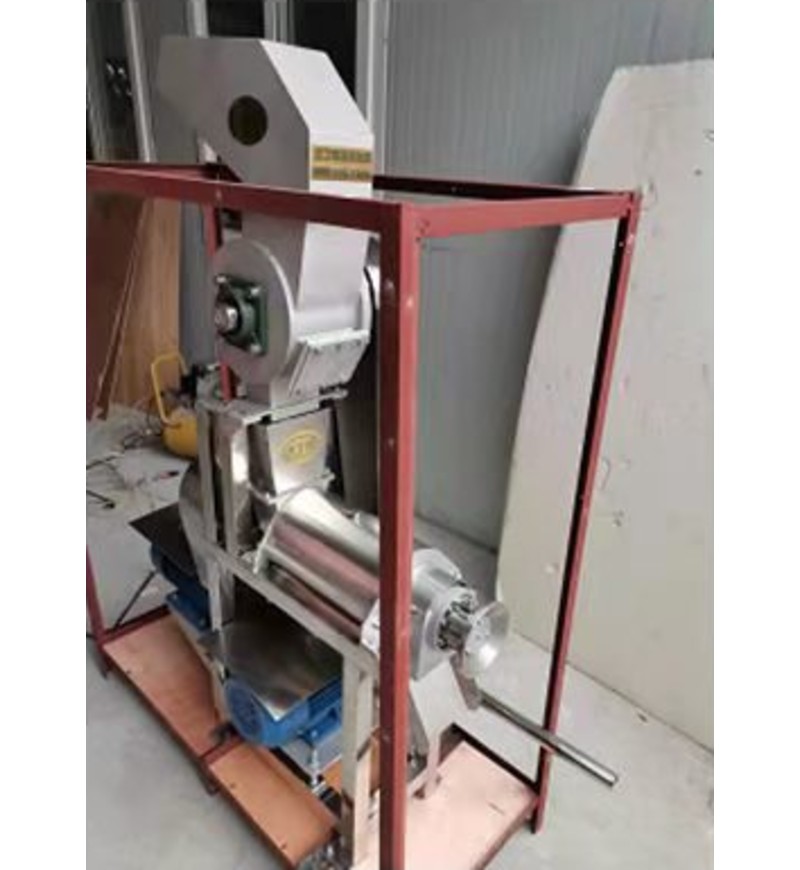
Working Principle
The main component of this equipment is that the bottom diameter of the screw is gradually increased along the direction of the slag outlet and the pitch of the screw is gradually reduced. When the material is pushed by the screw, the volume of the screw cavity is reduced, forming a squeeze of the material. The rotation direction of the screw spindle is clockwise when viewed from the feed hopper to the slag trough.
The raw materials are added to the hopper and pressed by the screw. The squeezed juice flows into the juicer at the bottom through the filter, while the waste is discharged through the annular gap formed between the screw and the pressure-regulated cone. The movement of the pressure regulating head along the axial direction can adjust the size of the gap. Used for clockwise (when looking from the slag discharge trough of the equipment to the end of the hopper, when the bearing seat is turned when the hand wheel shaft is turned, the pressure regulating head is turned to the left, and the gap is reduced, otherwise the gap becomes larger.) Change the size of the gap, that is, adjust the row Resistance of slag. The slag extraction rate can be changed, but if the gap is too small, under strong squeezing, part of the slag particles will be squeezed out through the filter together with the juice. Although the juice output increases, the quality of the juice decreases. The size of the gap should be determined. It depends on user’s specific process requirements.